MERCEDES LK, MK & SK Trucks Wiring Diagrams
LK, MK & SK ADM Wiring Diagram (adaptation module)
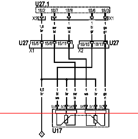
U27.1: ADM control unit adaptation module
U27: do chicote de adaptagao plug connection
XI: 18 pin plug connection
X2: 18 pin plug connection
LK, MK & SK Truck Distribution of XI plugs on the ADM control unit Adapter Module

Plug connection XI
Pin 1: Terminal 30
Pin 2: Not taken
Pin 3: Output Fault Indicator Lamp (MR, ADM)
Pin 4: Not Employed
Pin 5: Terminal 31
Pin b: Exit 'Engine brake 1'
Pin 7: Outlet Coolant Temperature
Pin 8: Power supply for the second gas pedal sensor signal
Pin 9: Exit Buzzer
Pin 10: Issuance of real value 2 Instrument cluster
Pin 11: Power supply for the first signal of the gas pedal sensor
Pin 12: Not Employed
Pin 13: Not Employed
Pin 14: Exit Warning message 'Oil pressure'
Pin 15: Terminal 15
LK, MK & SK Distribution of X2 plugs on the ADM control unit Adaptation Module

X2 plug connection
Pin 1: Not Employed
Pin 2: Exit 'Engine Brake'
Pin 3: Generator Reference point 'Terminal W'
Pin 4: Not Employed
Pin 5: Terminal 50 Immobilizer
Pin 6: Not Employed
Pin 7: Not Employed
Pin 8: Not Employed
Pin 9: Digital input 'KP in neutral'
Pin 10: Output 'Engine crankshaft speed signal'
Pin 11: Not Employed
Pin 12: 'ABS braking' input signal
Pin 13: Feedback from the first gas pedal sensor signal
Pin 14: Not Employed
Pin 15: Feedback of the second gas pedal sensor signal
Pin 16: Not Employed
Pin 17: Not Employed
Pin 18: Not taken
LK, MK & SK Distribution of X3 plugs on the ADM control unit Adaptation Module

LK, MK & SK Distribution of X4 plugs on the ADM control unit Adaptation Module

X4 plug connection
Pin 1: Not Employed
Pin 2: Not Employed
Pin 3: Not Employed
Pin 4: Not Employed
Pin 5: K-wire for diagnostics
Pin B: CAN bus mass connection
Pin 7: CAN High Bus
Pin 8: Not Busy
Pin 9: CAN Bus Low