NISSAN Almera Wiring Diagrams
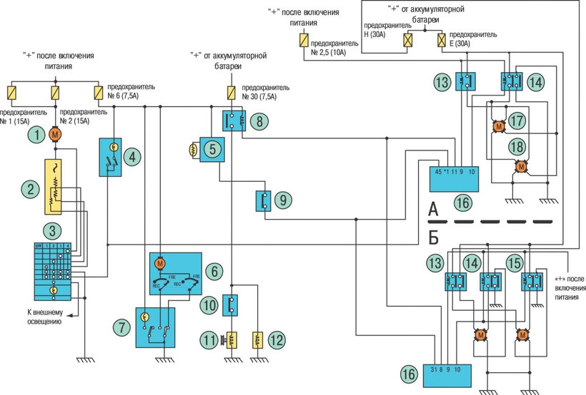
ALMERA Ignition Wiring Diagram
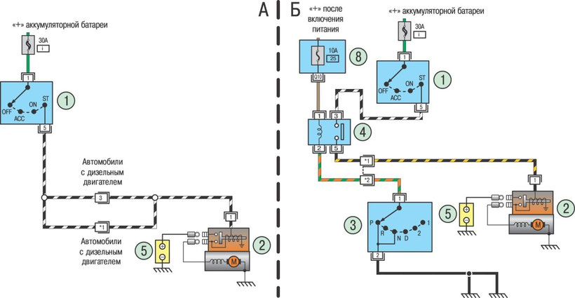
A - cars with manual transmission; B - cars with automatic transmission; 1 - ignition switch or instrument and starter; 2 - starter; 3 - selector; 4 - start blocking relay; 5 - rechargeable battery; 6 - mounting block in the car
ALMERA Battery Charging Circuit Diagram
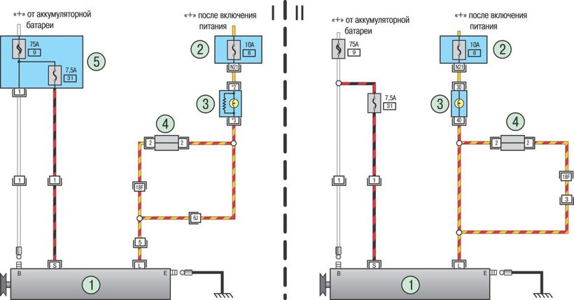
I - cars with a gasoline engine; II - cars with a diesel engine; 1 - generator; 2 - mounting block in the car; 3 - battery charging warning lamp; 4 - pin connector of the main wiring harness; 5 - mounting block in the engine compartment
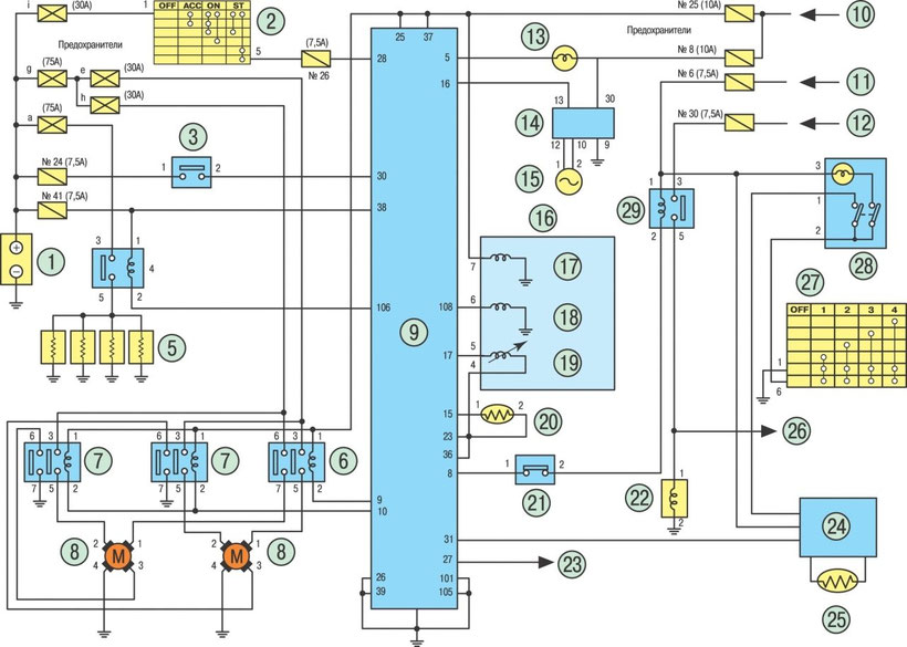
ALMERA ECCS engines GA14DE and GA16DE Schematic
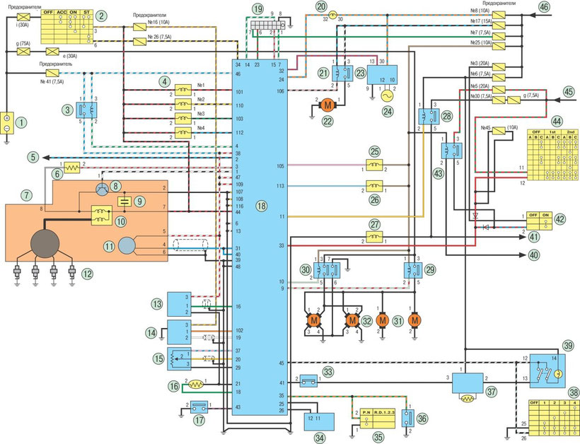
1 - rechargeable battery; 2 - ignition switch; 3 - power relay; 4 - fuel injectors; 5 - tachometer signal; 6 - control resistor; 7 - ignition distributor; 8 - switch (built into the ignition unit); 9 - capacitor; 10 - ignition coil; 11 - camshaft position sensor and engine crankshaft rotation speed; 12 - spark plugs; 13 - mass air flow meter; 14 - sensor oxygen content in the exhaust gases; 15 - throttle position sensor; 16 - coolant temperature sensor; 17 - pressure sensor in the power steering system; 18 - KSUD controller; 19 - diagnostic connector; 20 - warning lamp malfunction KSUD; 21 - fuel pump activation relay; 22 - fuel pump; 23 - tachometer; 24 - movement speed sensor; 25 - solenoid valve recirculation of exhaust gases and purge absorber; 26 - idling regulator; 27 - the regulator of the accelerated idling; 28 - the relay of turning on of the electromagnetic coupling of the compressor of the conditioner; 29 - relays for switching on the electric fans of the engine cooling system (on vehicles with a manual gearbox); 30 - dual relay on / electric fans of the engine cooling system (on cars with automatic transmission); 31 - one-speed electric fan of the engine cooling system; 32 - two-speed electric fan of the engine cooling system; 33 - compressor refrigerant pressure sensor; 34 - engine immobilizer; 35 - gear lever position sensor; 36 - selector lever position sensor; 37 - cabin temperature ECU with evaporator sensor; 38 - controls the heating and ventilation; 39 - climate control controls; 40 - to the time switch for switching on the heated rear window; 41 - to the air conditioning compressor; 42 - rear window heating switch; 43 - the relay for switching on the heated rear window; 44 - outdoor lighting switch; 45 - "+" battery; 46 - “+” after the ignition switch or “+” when the starter is turned on
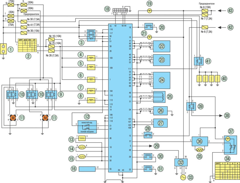
ALMERA CD20 Engine Management System Scheme
1 - rechargeable battery; 2 - switch devices and starter; 3 - left key sensor in the instrument switch and starter lock; 4 - pre and post-heating relay; 5 - glow plugs; 6 - relay switching on the electric fans of the engine cooling system at the 1st speed; 7 - a relay for switching on the electric fans of the engine cooling system at the 2nd speed; 8 - electric fans of the engine cooling system; 9 - electronic control unit (ECU); 10 - “+” after installing the key in the switch of the instrument switch and starter in the position “3” or “+” of the starter; 11 - “+” auxiliary equipment or “+” after turning on the instrument switch and starter; 12 - “+” from the battery; 13 - preheating indicator lamp; 14 - speedometer; 15 - vehicle speed sensor; 16 - fuel pump; 17 - diesel solenoid valve; 18 - solenoid valve regulating the fuel injection advance angle; 19 - engine crankshaft speed sensor; 20 - coolant temperature sensor; 21 - refrigerant pressure sensor; 22 - solenoid valve of accelerated idling; 23 - to the tachometer; 24 is a control unit for regulating the temperature of the air in the cabin; 25 - evaporator sensor; 26 - to the air conditioning compressor; 27 - ventilation controls in the cabin; 28 - air conditioning controls; 29 - the relay of turning on of the electromagnetic coupling of the compressor of the conditioner
ALMERA ABS Wiring Diagram
1 - ABS electronic control unit; 2 - relay unit; 3 - pump relay; 4 - electromagnetic valve control relay; 5 - front right wheel speed sensor; 6 - front left wheel speed sensor; 7 - speed sensor rotation of the rear right wheel; 8 - speed sensor rotation of the rear left wheel; 9 - brake light switch; 10 - diagnostic socket; 11 - ABS warning lamp; 12 - drain solenoid valve of the front left wheel; 13 - supplying solenoid valve of the front left wheel; 14 - drain solenoid valve of the front right wheel; 15 - supplying solenoid valve of the front right wheel; 16 - drain solenoid valve rear left wheel; 17 - supplying solenoid valve rear left wheel; 18 - drain solenoid valve rear right wheel; 19 - supplying solenoid valve of the rear right wheel; 20 - “+” after turning on the ignition switch or instrument switch and starter; 21 - “+” from the battery
ALMERA Air Conditioning System Diagram
A - gasoline engine; B - diesel engine; 1 - fan drive electric motor; 2 - the resistance of the fan motor; 3 - air conditioner mode switch; 4 - conditioner switch; 5 - control unit; 6 - electric motor for the air distribution damper drive; 7 - recirculation switch; 8 - air conditioner relay; 9 - double pressure sensor; 10 - air conditioner compressor temperature switch; 11 - air conditioning compressor; 12 - solenoid control valve; 13 - the first relay of the electric fan; 14 - the second relay of the electric fan; 15 - the third relay of the electric fan; 16 - electronic engine control unit; 17 - the first electric fan; 18 - second electric fan