VW POLO Sedan Wiring Diagrams
POLO SEDAN Scheme of the Electronic Engine Control System
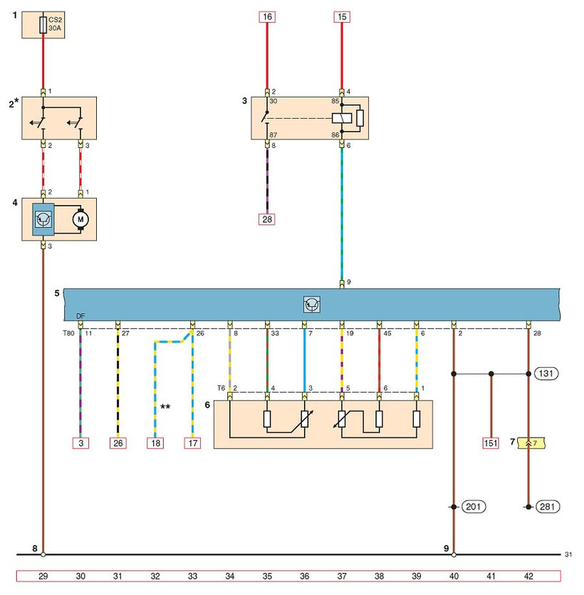
1 - mounting block C in the engine compartment; 2 - thermal switch of the radiator fan of the cooling system; 3 - power relay of terminal 30; 4 - radiator fan of the cooling system; 5 - engine control unit (ECU); 6 - pedal position sensor "gas"; 7 - 14-pin connector wiring; 8 - point of connection with the "mass" on the left spar; 9 - point of connection with the "mass" on the left in the engine compartment
POLO SEDAN Wiring Diagram of the Power Supply Control Unit
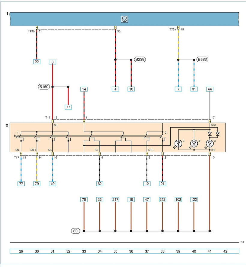
1 - power package control unit; 2 - lighting switch (1 - lighting switch; 2 - switch for fog lights and fog lights in the rear lamp; 3 - switch illumination LEDs)
POLO SEDAN Heater Connection Diagram
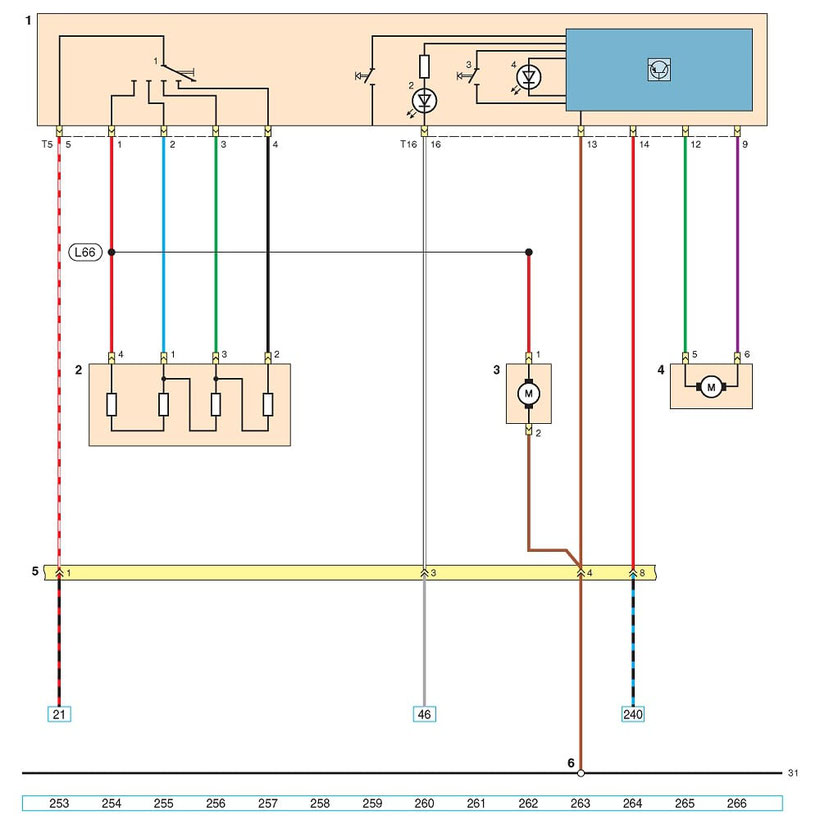
1 - heating and ventilation control unit (1 - heater fan switch; 2 - control unit illumination LED; 3 - recirculation mode switch; 4 - recirculation mode switch); 2 - additional heater fan resistor; 3 - heater fan electric motor; 4 - electric recirculation damper; 5 - 10-pin connector wiring; 6 - point of connection with the "mass" under the lining of the tunnel floor
POLO SEDAN Connection Diagram of the Instrument Cluster
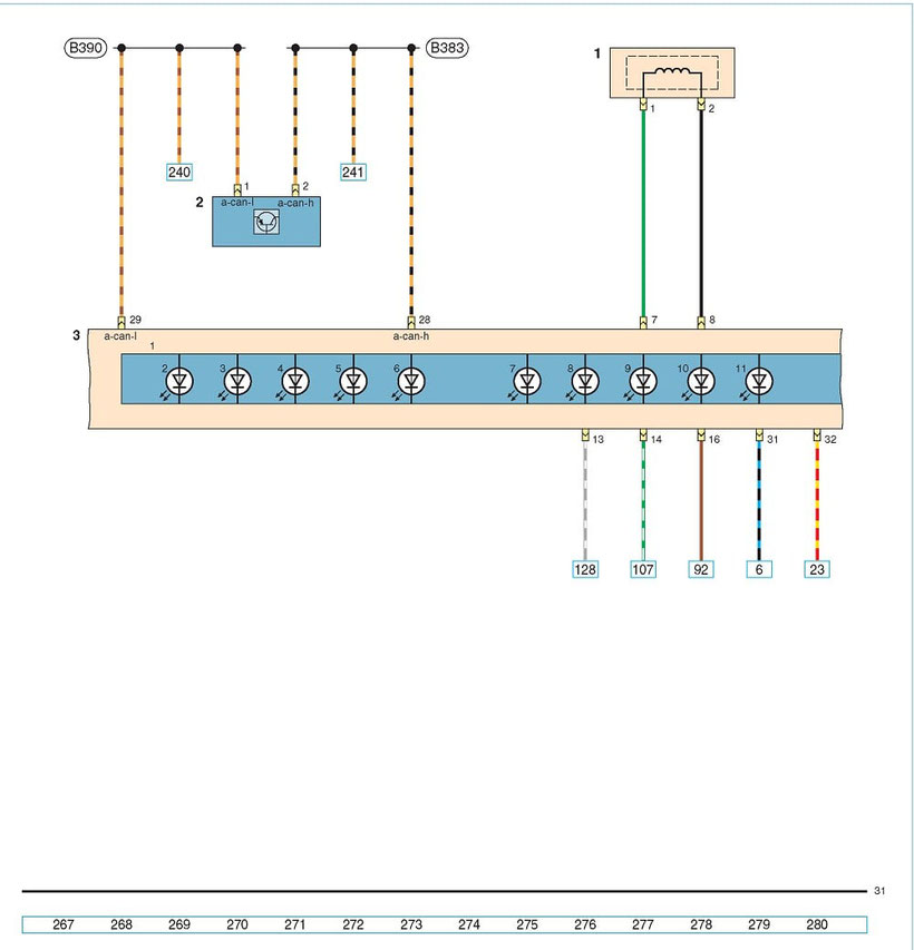
1 - immobilizer coupling coil; 2 - power steering control unit; 3 — instrument cluster (1 — instrument cluster control unit; 2 — unlocked door alarm device; 3 — tank low fuel level alarm device; 4 — seat belt safety alarm indicator; 5, left turn indicator warning lamp; 6 right turn indicator indicator; 7 - coolant temperature warning lamp; 8 - rear fog lamp warning light indicator; 9 - headlight high beam warning indicator; 10 - engine management system fault warning lamp; 11 - signal wort lack of battery charge)
POLO SEDAN Anti-Lock Braking System Wiring Diagram

1 - ABS control unit (1 - right front brake mechanism intake valve; 2 - right front brake mechanism exhaust valve; 3 - left front brake mechanism intake valve; 4 - left front brake valve exhaust valve; 5 - right rear brake intake valve ; 6 — left rear brake intake valve; 7 — right brake mechanism exhaust valve; 8 — left rear brake brake exhaust valve); 2 - mounting block B in the cabin; 3 - ECU; 4 - brake light switch (HL 1 brake pedal position sensor; HL 2 - brake light switch); 5 - point of connection with the "weight" on the left in the engine compartment
* with manual transmission