AUDI 80 Wiring Diagrams

A1 - control unit enrichment of the mixture; A2 - TSZ-H ignition switch; A3 - voltage regulator; B - battery; F1 - F17 - fuses (factory numbering); G - generator; H1 - beep; H2 - warning device for the fall of the brake fluid level; H3 - engine overheat alarm and coolant level drop; H4 - indicator of the right turn indicator; H5 - indicator of the left turn indicator; H6 - digital clock; H7 - clock lighting; H8 - alarm warning lamp; H9 - indicator of turning on dimensional illumination; H10 - coolant temperature gauge; H11 - fuel gauge in the tank; H12 - emergency oil pressure alarm; H13 - the indicator of the included parking brake; H14 - starter on indicator; H15 - generator malfunction indicator; H16 - speedometer; K1 - bus relay “X”; K2 - electronic relay buzzer; K3 - intake manifold preheating relay; K4 - control device indicator of emergency oil pressure; K5 - cooling fan relay; K6 - horn relay; K7 - electronic relay indicator; K8 - electronic wiper control relay; K9 - headlamp cleaning relay; L - ignition coil; M1 - starter; M2 - cooling fan; M3 - wiper; M4 - windscreen washer pump; M5 - headlight washer pump; M6 - heating system fan; P1 - Hall sensor ignition distributor; P2 - coolant temperature sensor; P3 - speedometer sensor; P4 - fuel level sensor; R1 - carburetor heater; R2 - intake manifold heater; R3 - dimmer control dimmer; R4 - cigarette lighter; R5 - rear window heater; S1 - ignition lock; S2 - thermocontact device; S3 - inlet manifold preheat switch; S4 - ignition distributor; S5 - 1.8 bar oil pressure sensor; S6 - oil pressure sensor 0.3 bar; S7 - Coolant fan temperature switch; S8 - brake light switch; S9 - light switch; S10 - contact group for flashing headlights; S11 - trunk light switch; S12 - reversing light switch; S13 - beep button; S14 - direction indicator switch; S15 - alarm switch; S16 – S19 - door switches of the left front, left rear, right front and right rear doors, respectively; S20 - wiper switch; S21 - coolant level sensor; S22 - brake fluid level sensor; S23 - button to install an electronic clock; S24 - parking brake activation sensor; S25 - starter operation sensor; S26 - heating system fan switch; S27 - rear window heater switch; W1 - left rear turn indicator; W2 - left rear position lamp; W3 – W4 - brake lights; W5 - right rear position lamp; W6 - Right rear turn indicator; W7, W8 - left headlight; W9, W10 - right headlight; W11, W12 - left and right front marker lights; W13 - glove box lighting lamp; W14 - shield lighting lamps; W15 - boot light; W16 - engine compartment lighting lamp; W17, W18 - reversing lights; W19, W20 - right and left front direction indicators; W21 - interior lighting; W22 – W27 - illumination lamps of the instrument cluster; W28 - cigarette lighter lamp; X1 – X19 - connectors (the color in the diagram corresponds to the color of the connector case), installed: X1 - on the right of the apron; X2 - about the distributor of ignition; X3 - about the carburetor; X4 - near the valve Y2; X5 - near the intake manifold; X6, X7, X9, X11, X12 - near the mounting block; X8 - in the trunk on the left; X10, X13, X17 - left behind the dashboard; X14 - on the left behind the instrument cluster; X16 - on the instrument cluster (yellow); X18 - on the instrument cluster (blue); X19 - in the middle of the instrument panel; Y1 - valve enrichment mixture; Y2 - excess air valve; Y3 - carburetor jet valve
AUDI 80 Wiring Diagram of the Door Lock System
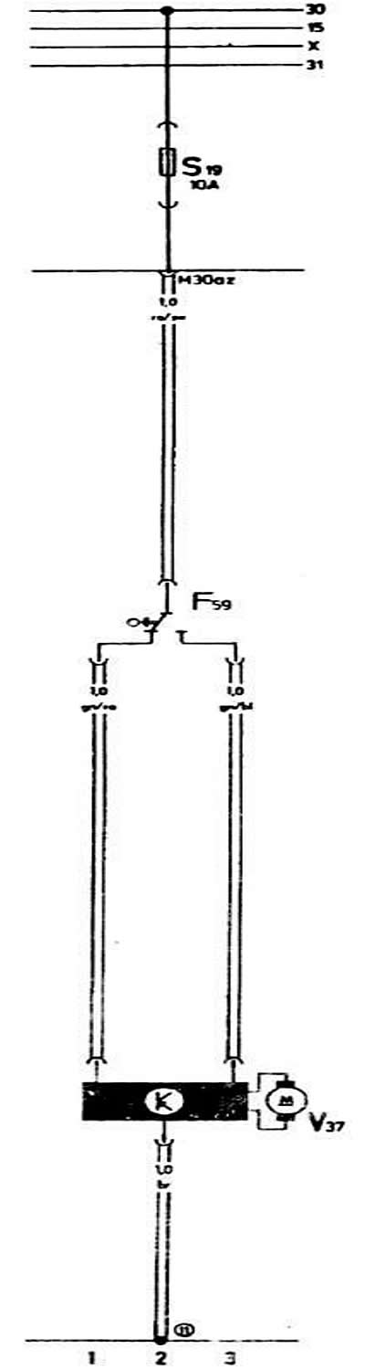
F59 Door Lock Interlock Switch 1-3
S19 Fuse in the mounting block
V37 Electric Pneumatic Door Lock 1-3
(11) Junction to ground in the trunk
AUDI 80 Wiring Scheme of Inclusion of Fog Lamps since 1985
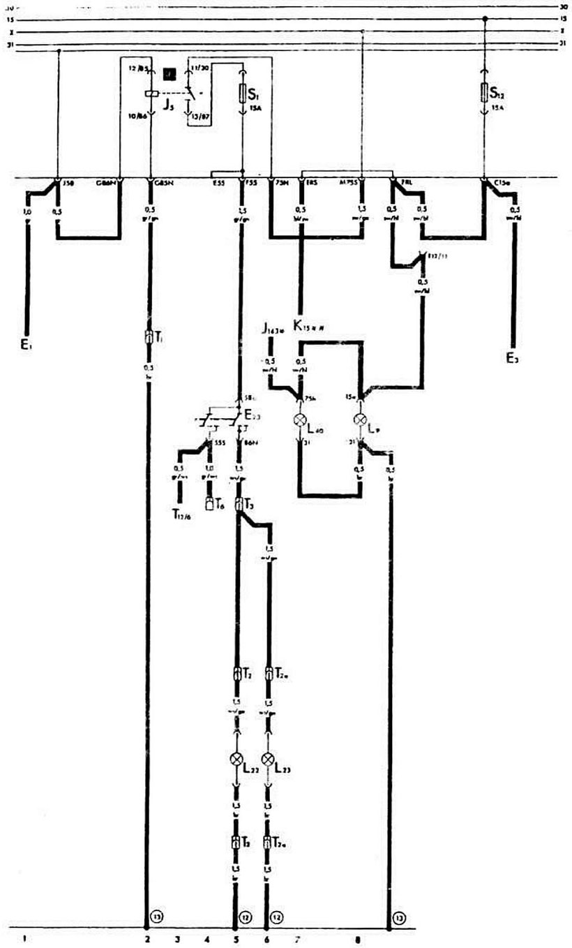
E1 Outdoor Lighting Switch 1
E3 Alarm Switch 10
E23 Foglight and rear fog light switch 4.5
J5 Relay Fog light 2.3
J143 Electronic control unit for idle speed control valve * 6
K15 Control lamp cover carburetor air damper ** 7
L9 Outdoor Illumination Switch Lamp 8
L22 Left fog lamp 5
L23 Fog light, right 6
T12 / 12-pin instrument cluster connector
(12) Connection to ground by soldering in the left front bundle of wires
(13) Junction to ground by soldering in the wiring harness of the instrument cluster
[1] Fog light relay
L40 Fog light switch and rear fog light illumination lamp 7
S1.S12 Fuses on the mounting block
T1 Single plug (red-white, behind the instrument cluster)
T2 2-pin connector (on the left in the compartment of the power unit)
T2a 2-pin connector (to the right in the compartment of the power unit)
T3 3-pin plug (yellow, behind instrument cluster)
T6 6-pin plug (brown, behind instrument cluster)
AUDI 80 Circuit Diagram of Automatic Stop-Start Engine Activation

B To the starter 12
E15 Rear window heating switch 9, 10
E84 Engine start and start switch 9
F52 Coolant Temperature Sensor Light Sensor 2
F71 Clutch deactivation sensor automatic engine stop and start 12
F72 Accelerator pedal position sensor automatic engine stop and start 12
054 Speed sensor movement automatic stop and start engine 5
H1 To beep 10
J53 Starter start relay 11-13
J81 Intake manifold preheating relay 2,3
J107 Control unit for automatic stop and start of the engine 4-10
J108 Automatic Stop and Start Stop Diode 8
J109 Auxiliary relay for switching on the heated rear window 8.9
K43 To control lamp low coolant temperature 1
N Ignition Coil
to terminal "15" of the ignition coil 1
to terminal 1 of the ignition coil 6
N51 To inlet duct heating resistor 3
S9 Fuse in the fuse box of the mounting block
T1 Single plug connector (behind instrument cluster)
T1a Single plug connector (behind instrument cluster)
T1b Single plug connector (behind instrument cluster)
T1s Single Plug Connector (behind instrument cluster)
T1d Single plug connector (behind instrument cluster)
T1e Single plug connector (behind instrument cluster)
T4 4-pin plug (behind instrument cluster)
Z1 To rear window element 9
(8) Ground connection for instrument cluster
(10) Connection to ground in the engine compartment on the right
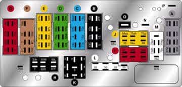
The layout of the connectors and their contacts in the mounting block of AUDI 80
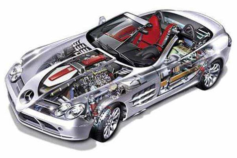
Audi 80 Review
Some AUDI 80 Wiring Diagrams are above the page.
Audi 80 models are equipped with five petrol engines. The range of engines extends from economical 4-cylinder engines to comfortable and powerful options, such as single-row 5-cylinder and V-shaped 6-cylinder engines.
The 5-speed manual gearbox is standard on most Audi 80 models. Four front-wheel drive models with petrol engines are offered with special equipment - an electronically / hydraulically controlled four-speed automatic gearbox. It is equipped with two programs of movement: "E" (economical) and "S" (sports).