DAEWOO Nexia Wiring Diagrams
NEXIA Wiring Diagram of Ignition, Starter, Generator
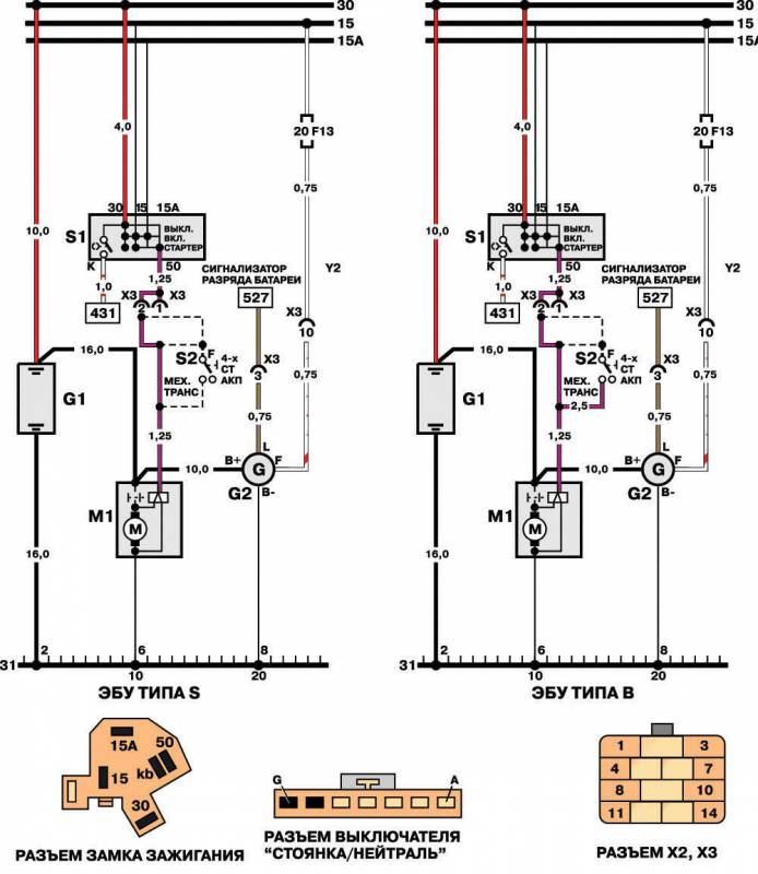
G1 Battery
M1 Starter
S1 Ignition switch
82 "Parking / Neutral" switch
NEXIA Ignition System Diagram
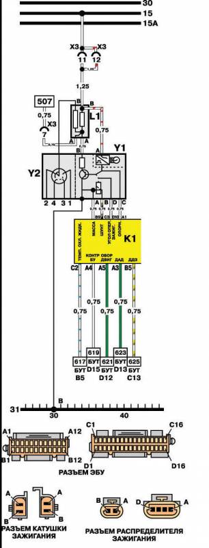
K1 ECU
11 Ignition coil
Y1 Ignition unit
Y2 Distributor, ignition
NEXIA Fuel Injectors Schematics

K1 ECU
NEXIA Temperature, Pressure, Speed, Damper Sensors Scheme

M2 Valve idling
P1 Vehicle speed sensor
P2 Coolant Temperature Sensor
RZ Absolute pressure sensor in intake manifold
HZ Octane Corrector Switch Connector
P4 Throttle Position Sensor
P5 Wiring for oxygen concentration sensor
P5-1 Oxygen concentration sensor (1.5-liter engines type DOCH)
P5-2 CO-potentiometer (1.5-liter engines)
P6 Intake air temperature sensor
NEXIA Diagrams of the Diagnostic System, the Lock of the Torque Converter, Fuel
K1 ECU
MZ fuel pump motor
S2 Parking / Neutral Switch
S4 Oil pressure switch
X1 Onboard Diagnostic System Connector
X2 Fuel Pump Test Connector
NEXIA Transmission Control Wiring Diagram, Anti-Theft Device, Airbag

K18 TRANSMISSION CONTROL UNIT
K19 CONTROL UNIT OF ANTI-THEFT DEVICE
K20 SAFETY PAD CONTROL UNIT
P1 CAR SPEED SENSOR
R8 SHOULDER
R9 CONTACT COIL
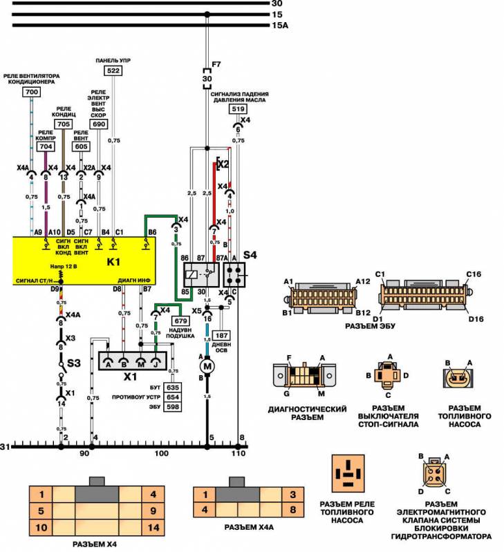
NEXIA Diagrams of Diagnostic Systems, Blocking Torque Converter, Fuel

K1 ECU
K2 Fuel Pump Relay
MZ fuel pump motor
52 "Parking / Neutral" switch
53 brake light switch
S4 Oil pressure switch
X1 Onboard Diagnostic System Connector
X2 Fuel Pump Test Connector
Y4 Solenoid lockout solenoid valve
Acc (Thursday, 21 May 2026 22:09)
Acc