
RENAULT Logan Wiring Diagrams
LOGAN Battery Charging Circuit Diagram
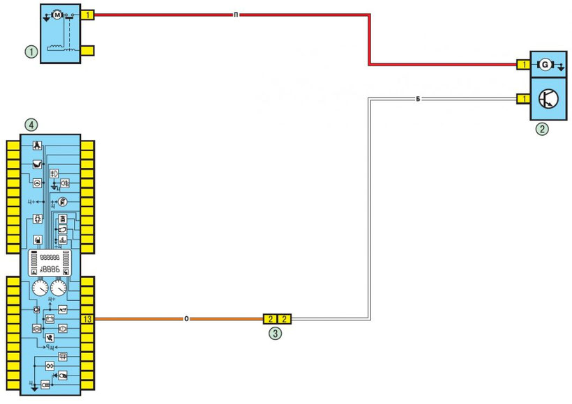
1 - starter; 2 - generator; 3 - connector of the electrical wiring of the engine compartment / cabin (monoblock); 4 - the instrument cluster.
LOGAN Fuel Pump and Fuel Level Sensor Diagram

1 - instrument cluster; 2 - connector of the electrical system of the engine compartment / compartment (monoblock); 3 - electrical wiring connector dashboard / left rear; 4 - fuel pump and fuel level sensor.
LOGAN Engine Management System Schematics

1 - 597B fuse box in the engine compartment; 2- relay block 784 in the engine compartment, relay 700; 3-nozzle 1st cylinder; 4- fuse box in the cabin; 5- connector of the engine compartment / passenger compartment (monoblock); 6- relay unit 1047 in the engine compartment, relays 236 and 238; 7 — relay block 784 in the engine compartment, relay 474; 8-refrigerant pressure sensor (cars with air conditioning system); 9- nozzle of the 2nd cylinder; 10 - fuel pump and fuel level sensor: 11 - electrical connector dashboard / left rear; 12- relay block in the engine compartment, relay 234; 13-throttle position sensor; 14 - a nozzle of the 3rd cylinder; 15- air conditioning control panel; 16-knock sensor; 17 crankshaft position sensor; 18-ignition module; 19 air temperature sensor; 20 - nozzle of the 4th cylinder; 21 - adsorber; 22 - stepper motor regulator idling; 23 - instrument cluster; 24 - ECU; 25 - diagnostic oxygen concentration sensor (lambda probe); 26 - cabin switching unit; 27 - coolant temperature sensor; 28 - pressure switch of the power steering system; 29 - oxygen concentration sensor (lambda probe) of the engine management system; 30 - diagnostic connector; 31 - speed sensor; 32 - absolute pressure sensor in the intake pipe.
LOGAN Engine Start System Scheme
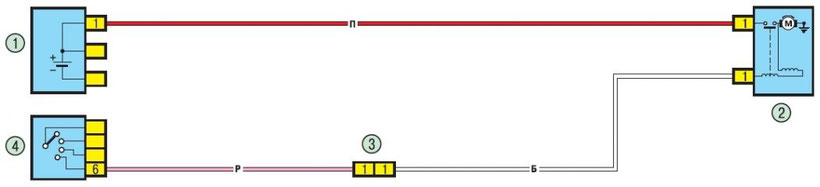
1 - rechargeable battery; 2 - starter; 3 - connector of the electrical wiring of the engine compartment / cabin (monoblock); 4 - ignition switch (lock).
LOGAN Direction Indicators and Alarms Wiring Diagram
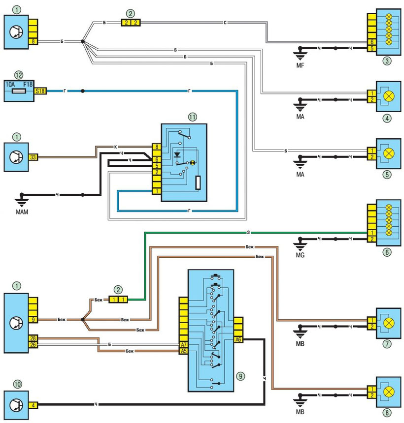
1 - cabin switching unit; 2- dashboard / left rear wiring connector; 3- right rear light; 4- right front turn indicator; 5- right turn signal repeater; 6-left rear light; 7-left front turn signal; 8-left turn signal repeater; 9 - the lever of the switch of external illumination and turn indicators with the button of inclusion of a sound signal; 10 - diagnostic connector; 11 - alarm switch; 12- fuse box in the cabin.
LOGAN Overall Light Wiring Diagram
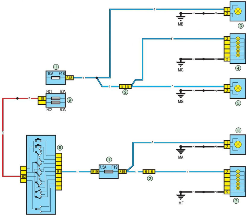
1 - fuse box in the cabin; 2- wiring connector of the instrument panel / left rear; 3-dimensional light of the left front headlight; 4-left rear light; 5- license plate lighting; 6-dimensional light of the right front headlight; 7 - right rear light; 8- the lever of the switch of external illumination and direction indicators with the button of the sound signal on; 9- fuse block 597A in the engine compartment.