BMW 3 E30 Wiring Diagrams
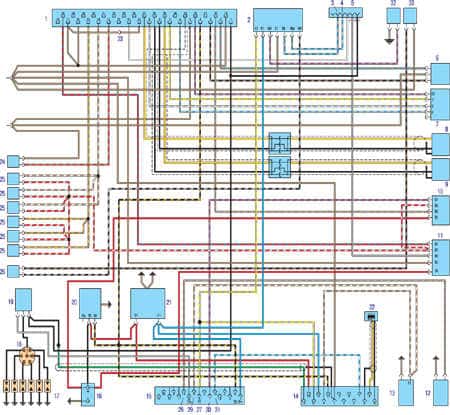
BMW 3 E30 Headlights & Taillights Wiring Diagram
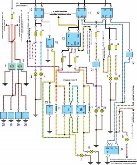
1. Left ceiling interior lighting
2. Right ceiling interior lighting
3. The high beam lamp of the left headlight
4. High beam right headlight bulb
5. Low beam headlamp
6. Low beam headlamp bulb
7. Lamp fog light left headlight
8. Lamp fog light right headlamp
9. Ashtray lamp
10. Headlight Relay
11. Relay low beam headlights
12. Fog light relay
13. Indicator lamp for lighting
14. Low-beam headlamp relay
15. Relay low beam right headlamp
16. Additional resistor
17. Additional resistor
18. Main / dipped beam switch
19. Left front door limit switch
20. Right front door limit switch
21. Rear fog light switch
22. Front fog light switch
23. Dipped beam switch
24. Instrument Panel Light Control and Front Fog Light Switch
25. Left rear door limit switch
26. Right rear door limit switch
27. Bulb fog lamp left rear light
28. Fog light lamp right rear lamp
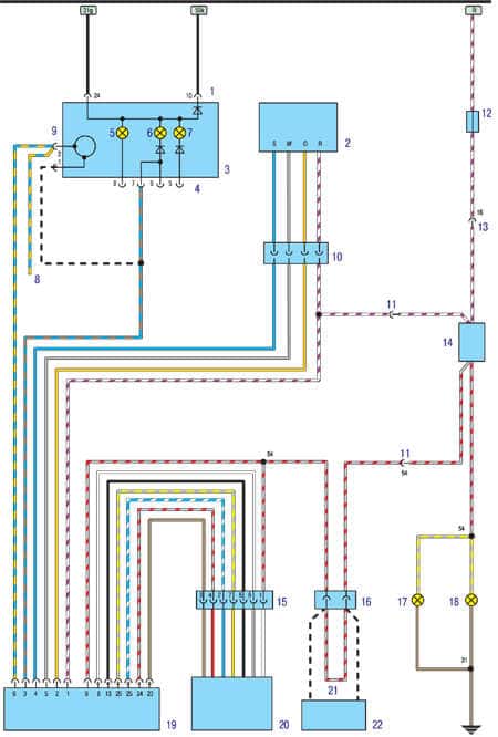
BMW 3 E30 Diagnostic unit; signal reverse, braking; power mirrors Wiring Diagram
1. Diagnostic unit
2. Bulb light left rear light
3. Right side light lamp rear light
4. A lamp of light of a backing of the right lamp
5. A lamp of light of a backing of the left lamp
6. The lamp of the right ceiling of the license plate
7. The lamp of the left ceiling of the license plate
8. Block additional braking signal
9. Lamp brake light left rear light
10. Lamp brake light right rear lamp
11. Lamp on / off unit
12. Reversing light switch 1
13. Reversing light switch 2
14. Switch for rear lights and license plate light
15. Brake light switch
16. Liquid level sensor in the washer tank
17. Liquid level sensor in engine cooling system
18. Engine oil level sensor
19. Rear-view mirror drive switch
20. Rear-view mirror drive motor
21. Rear-view mirror drive motor (optional)
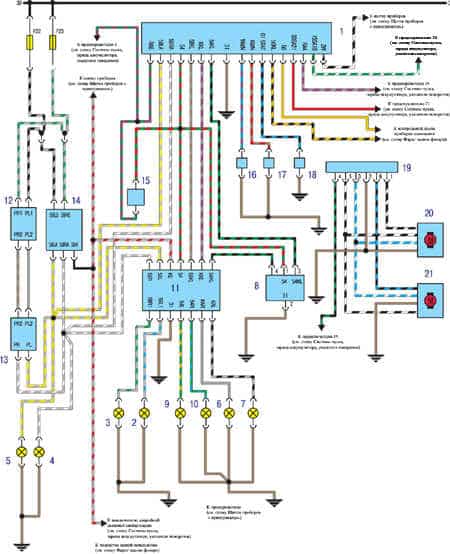
BMW 3 E30 Instrument panel and cigarette lighter Wiring Diagram
a - parking brake warning lamp
b - brake fluid level indicator lamp
c - oil pressure warning lamp
d - the main control lamp
e - control lamp of the next maintenance
f - brake wear indicator lamp
g - coolant temperature gauge
h - fuel reserve warning lamp
i - fuel gauge
j - tachometer
k - econometer
l - indicator lamp left direction indicator
m - indicator lamp right turn indicator
n - speedometer
o - driving lamp headlights
p - front fog lamp indicator
q - indicator lamp rear fog lights
r - battery charge indicator lamp
s - instrument panel lighting
1. Instrument panel
2. Parking Brake Switch
3. Brake fluid level sensor
4. Oil pressure sensor
5. Coolant temperature sensor
6. Brake pad wear sensor, rear right wheel
7. Brake pad wear sensor, left front wheel
8. Fuel level sensor 1
9. Fuel level sensor 2
10. Speedometer sensor
11. cigarette lighter
12. Illumination of the heater control panel
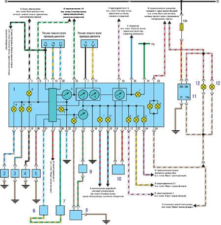
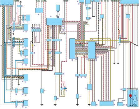
BMW 3 E30 Motronic engine management system Wiring Diagram
1. Electronic engine control unit
2. The control unit crankshaft speed
3. Temperature sensor connector
4. A / C connector
5. Connector to Transmission Wire Harness
6. Throttle Position Sensor
7. Air flow meter
8. Crankshaft speed sensor
9. Ignition timing sensor
10. Relay 1
11. Relay 2
12. Oil pressure sensor
13. Temperature sensor of the electronic engine control unit
14. Diagnostic connector
15. Distribution block
16. Battery
17. Spark plugs
18. Ignition distributor
19. Ignition coil
20. Starter
21. Generator
22. Position sensor
23. Connector (on automatic transmission disconnected)
24. Coolant temperature sensor
25. Fuel Injector
26. Solenoid
27. Distribution block
28. Connector for oil pressure sensor
29. Connector for temperature sensor
30. Connector for fuel pump
31. Socket for connecting a warning lamp for regular maintenance
32. Drive
33. Contact temperature sensor
BMW 3 E30 Cruise control system Wiring Diagram
1. Pin connector
2. Steering column switch
3. Instrument panel
4. Connectors position indicator automatic transmission selector
5. Control lamp position D selector automatic transmission
6. Control lamp of position N of the automatic transmission selector
7. Control lamp of position R selector of automatic transmission
8. Speedometer connector
9. 2-pin connector on the instrument panel
10. Steering column switch connector
11. Connector (special)
12. Steering column switch
13. Connector (back leading to central chati)
14. Brake light switch
15. Drive connector
16. Clutch Lock Switch Connector
17. A lamp of a signal of braking of the left lamp
18. Lamp lamp brake light right lamp
19. Cruise control unit
20. Power cruise control
21. Jumper (only on cars with automatic transmission)
22. Interlock Clutch Switch
BMW 3 E30 Central locking, security alarm, on-board computer Wiring Diagram
1. Pin connector
2. Pin connector for auxiliary equipment
3. Pin connector of the central locking control unit
4. Central locking control unit (front plate on the A-pillar)
5. Pin wire connector from the lock driver's door
6. 13-pin connector from the control unit central lock to the driver's door wiring
7. Pin connector from control unit central lock to the passenger door wiring
8. Pin connector for lock wiring driver's door to switch
9. Central locking switch / stop mechanism (mounted on the lock driver's door)
10. 6-pin electric drive connector driver's door lock
11. Power driver door lock
12. Microswitch pin connector passenger door lock
13. Micro switch for passenger door lock
14. Pin connector electric passenger door lock
15. Power passenger door lock
16. Connector 6-pin electric boot lid lock
17. Power tailgate lock
18. Socket 6-pin electric drive lock tank filler
19. Electric lock of the tank filler neck
20. Pin connector of the electric drive of the rear left door lock
21. Power rear left door lock
22. Connector 6-pin electric drive lock the rear right door
23. Connector 7 pin rear wiring right door
24. Connector 7 pin rear left door wiring
25. Power lock rear right door
26. Rear window heater switch
27. The control unit burglar alarm (left on the steering column)
28. 26-pin connector for the burglar alarm control unit
29. Socket 4 pin wiring for relay mounting block
30. 4-pin connector of the burglar alarm control unit
31. Pin connector main wiring harness
32. Security alarm LED
33. Luggage compartment lighting connector
34. Lamp luggage compartment lighting
35. Front left door limit switch
36. Front right door limit switch
37. Rear Limit Switch left door
38. Rear Limit Switch right door
39. Luggage limit switch branches
40. Limit switch hood
41. Rear window heater
42. Onboard computer / security alarm wiring connector
43. Beep
44. LED pin connector
45. Diode
46. Security alarm / central locking contact connector
47. Sound alarm (left on the steering column)
48. Sound alarm connector
49. Pin connector wiring engine management system L-Jetronic
50. Ignition switch
51. Remote switch on-board computer
52. Pin connector wires from the ambient air temperature sensor to the onboard computer
53. Wire connector to ambient temperature sensor
54. Ambient temperature sensor
55. Pin connector wires additional heater outdoor antenna
56. The control unit of the heating of a parked car (located under the right seat)
57. Pin connector of the control unit
58. Relay heater parked car
59. Onboard computer / auxiliary heater wiring connector
60, 61. Pin connector wiring instrument panel
62. On-board computer (located on the instrument panel on the right)
63. Onboard computer connector
64. Pin connector instrument panel
65. Instrument panel
66. Pin connector instrument panel
67. Pin connector digital clock
68. Heater wire connector
69. Pin connector of the fuel pump wiring
70. Heater wiring connector
71. Heater add-on resistor
72. Temperature sensor
73. Heater motor
74. The switch of the heater of the parked car in case of overheating
75. Insert parked car heater
76. Heater unit
77. Fuel pump
78. Contact plug remote switch onboard computer
79. Pin connector volume control depending on the speed
80. Cruise control wire connector
81. Fuel level sensor
82. Speed sensor
83. 4-pin digital clock wire connector
84. 2-pin digital clock wire connector
85. Digital clock
BMW 3 E30 History
Some BMW 3 E30 Wiring Diagrams are above the page.
E30 first appeared in January 1983 in a single version of the 2-door coupe.
Only a year later, in January 1984, buyers had the opportunity to choose with the advent of the 4-door sedan, which at once greatly increased the popularity of the model. In 1986, the E30 convertible went on sale. And only close to the end of the production of E30 Bavarians pleased generalist.
True, the luggage compartment could not boast a significant amount, but the car looked just great. Another rare modification - the all-wheel drive model 325iX - borrowed the transmission from the all-wheel drive "five" in the back of the E34. Produced and diesel versions of the sedan.