MERCEDES ACTROS Truck Wiring Diagrams
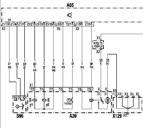
ACTROS Nummek Units Wiring Diagram
A39: Nummek Units
A65: Rear NM module
F73: Fuse Bridge "Nummek"
S96: Nummek bridge overload switch
X129: Electricity distributor 'terminal 31'
yl: Solenoid valve
y2: Solenoidvalve
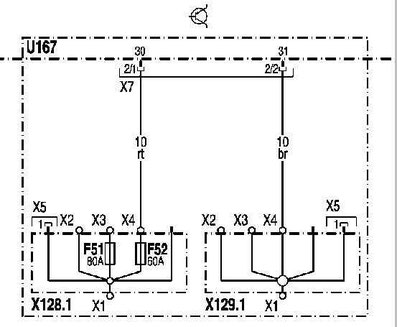
ACTROS Power Supply Rear Module HM Schematics
A65: Control unit Rear HM module
F51: FM control unit fuse front module, terminal 30
F52: Control unit fuse Rear module HM, terminal 30
U167: Valid only for vehicles with integral rear
X128: Power Distributor 'Terminal 30'
X128.1: Power Distributor 'Terminal 30' (Integral Rear)
X129: Power Distributor 'Terminal 31'
X129.1: Power Distributor 'Terminal 31' (Integral Rear)
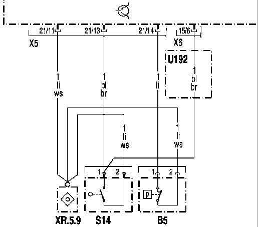
ACTROS Pressure Sensor "Parking Brake" Circuit Diagram
A65: Control unit Rear HM module
B5: Pressure Sensor 'Parking Brake'
S14: Cross wheel differential lock control switch on the rear axle 1.
U192: Only for the type of Truck 6x2
XR.5.9: Wire Adapter
ACTROS Pressure Sensor Tilting Device Control Schematics
A65: Control unit Rear HM module
B18: Pressure Sensor 'Tilting Device Control'
S15: Cross wheel differential lock control switch on the rear axle 2.
S17: Center differential lockout control switch in transfer case
S18: Rear Axle Differential Lock Control Switch
XR.5.3: Adhesive Wire Connector
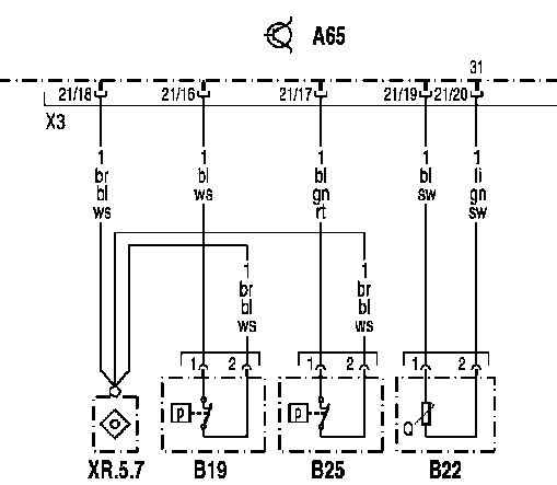
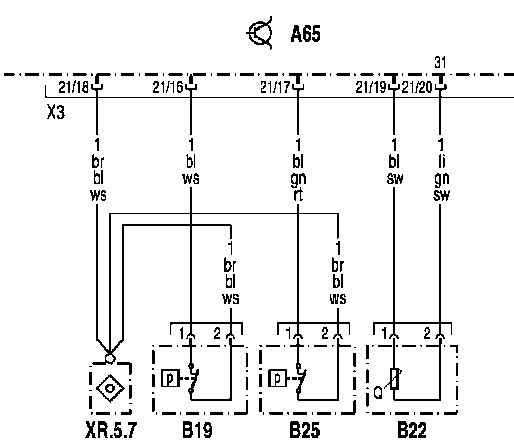
ACTROS Pressure Sensor "Secondary Consumers" Scheme
A65: Control unit Rear NM module
B19: Pressure sensor 'Secondary consumers'
B22: Fuel Level Sensor
B25: Pressure sensor 'Brake circuit 3'
XR.5.7: Adhesive Wire Connector
ACTROS Fuel Level Sensor Schematic
A65: Control unit Rear HM module
B19: Pressure sensor 'Secondary consumers'
B22: Fuel Level Sensor
B25: Pressure sensor 'Brake circuit 3'
XR.5.7: Adhesive Wire Connector

