MERCEDES ATRON Truck Wiring Diagram
ATRON MR Wiring Diagram (motor control)
A95: SCR module on the frame (Euro 4 or Euro 5)
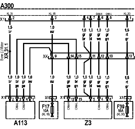
F39: Fuse Terminal 30
HC: Plug-in connector 'driver chassis cab'
XR.31.1: Wiring place '31'
ATRON Fragment of the WSP Wiring Diagram - Immobilizer
AZ: FR control unit motion control system
A139: MR control unit engine management system
A42: Immobilizer reading unit
S1: Ignition lock
ATRON NOx Sensor Schematics
A300: SCR-LO control unit
A113: NOx sensor
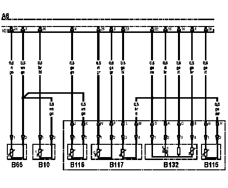
ATRON Fuel Temperature Sensor Circuit Diagram
Ab: MR control unit engine management system
X2: Plug connection (55-pin)
B10: fuel temperature sensor
Specified values and parameters:
- The specified resistance is approx. at 25 ° С: 1975 - 2155 Ohm
- The specified resistance is approx. at 60 ° C: 575 - 613 Ohm
- The specified resistance is approx. at 90 ° C: 239 - 249 Ohm
- The specified resistance is approx. at 120 ° С: 111 - 117 Ohm
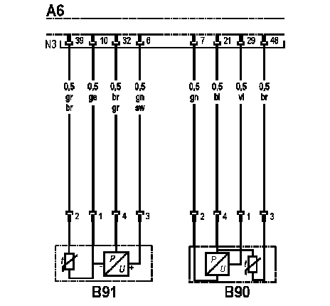
ATRON Oil Temperature Sensor Wiring Diagram
A6: MR control unit engine management system
B91: Oil Temperature Sensor
B91: Oil Pressure Sensor
Specified values and parameters:
- The specified resistance is approx. at 25 ° С: 1975 - 2155 Ohm
- The specified resistance is approx. at 60 ° C: 575 - 613 Ohm
- The specified resistance is approx. at 90 ° C: 239 - 249 Ohm
- The specified resistance is approx. at 120 ° С: 111 - 117 Ohm


