MERCEDES AXOR Wiring Diagrams
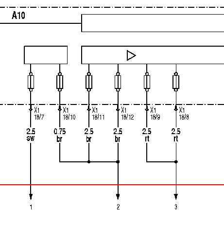
AXOR Power Supply on the ABS Control Unit Wiring Diagram
Power supply on the ABS control unit anti-lock system
A10: ABS control unit anti-lock system
XI: Plug-in connection on the ABS control unit anti-lock system
XI 18/7: Clamp 15
XI 18/8: ZO terminal
XI 18/9: Terminal 30a
XI 18/10, XI 18/11, XI 18/12: Terminal 31
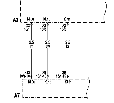
1: Connection to terminal X9 18 / 1-18 on the base module
2: Connection to terminal X8 15 / 1-15 on the base module
3: Connection to terminal X13 18 / 1-18 on the base module
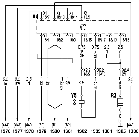
AXOR Wiring Diagram of FU Electric Torch Air Heater
A4: FLA control unit electric torch air heater
R3: Incandescent Torch Candle
Y5: Electromagnetic solenoid air heater solenoid valve
[444]: Wire to terminal 31
[447]: Wire to terminal 15
[449]: Wire to terminal 30
[80]: CAN-H wire to FR control unit motion control system
[81]: CAN-GND wire to FR control unit motion control system
[82]: CAN-L wire to FR control unit motion control system
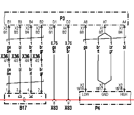
AXOR Wiring Diagram of the Modular Tachograph TCO
RZ: MTCO modular tachograph
P4: INS instrument cluster
B17: Speed sensor
X83: Connection for Additional Recorder
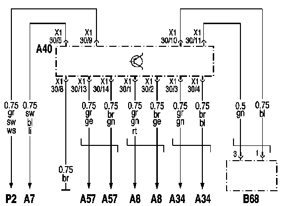
AXOR SRS Airbag Wiring Diagram
A40: Airbag control unit (under the floor mat)
B68: Airbag for driver
XI 30/1: Driver Belt Tensioner (+)
XI 30/2: Driver Belt Tensioner (-)
XI 30/3: Front passenger belt tensioner (+)
XI 30/4: Front passenger belt tensioner (-)
XI 30/5: Power Supply (+)
XI 30/8: Power Supply (-)
XI 30/9: Large instrument cluster, wire K for diagnostics
XI 30/10: Airbag for driver (+)
XI 30/11: Airbag for driver (-)
XI 30/13: Seat belt tensioner for the middle seat (+)
XI 30/14: Belt tensioner for the seat in the middle (-)
AXOR Schematics of Motion Control FR
AZ: FR control unit motion control system
A7: Base Module

