MERCEDES UNIMOG Wiring Diagrams
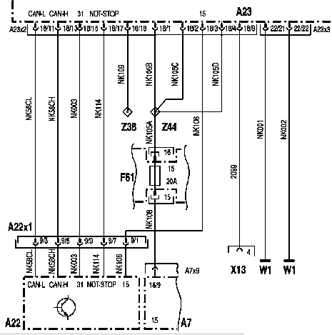
UNIMOG Fragment of Wiring Diagram of Power Supply Circuitry and CAN bus
A23: Power part 'Hydraulics'
A22: Joystick Module
A22x1: Hydraulic Joystick Connector, 9-pin
A7: Base Module
F61: Fuse, terminal 15
W1: Mass point in the center console
X13: Diagnostic Connector (pin 4)
Z38: Reference point 'Terminal W'
Z44: Reference point 15 'Hydraulics'
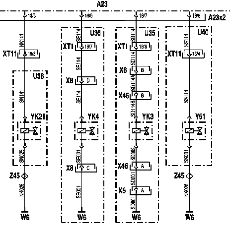
UNIMOG Fragment of Schematics of the Proportional Valves
A23: Power part 'Hydraulics'
YK21: Proportional valve, circuit 1
YK3: Proportional valve, circuit 3
YK4: Proportional valve, circuit 4
Y51: Proportional valve 'Snow Plow Unloading'
W6: Front frame mass point
XT1: Plug-in connection 'Driver's cab - chassis', 18-pin
XT11: Plug-in connection 'Driver's cab - chassis', 18-pin
X8: Hydraulics plug-in connection, 8-pin
X4b: Plug-in connection 'Proportional valve for ontura 3', 2-pin
Z45: Reference Point 31 'Hydraulic Solenoid Valves'
Note:
Proportional valve YK21 and solenoid valve YM17 cannot be installed together.
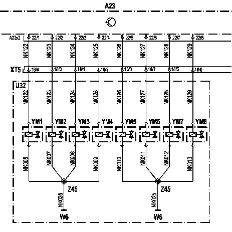
UNIMOG Part of Scheme of the Electrical Circuit of the Solenoid Valves YM1 - YM8
A23: Power part 'Hydraulics'
YM1-YM8: Solenoid Valves
W6: Front frame mass point
XT5: Plug-in connection 'Driver's cab - chassis', 18-pin
Z45: Reference Point 31 'Hydraulic Solenoid Valves'
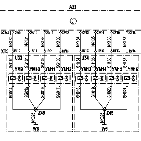
UNIMOG Part of Circuit Diagram of the Electrical Circuit of the Solenoid Valves YM9 - YM16
A23: Power part 'Hydraulics'
YM9-YM16: Solenoid Valves
W6: Front frame mass point
XT5: Plug-in connection 'Driver's cab - chassis', 18-pin
Z45: Reference Point 31 'Hydraulic Solenoid Valves'
Mercedes Unimog History
In October 1946, the first test ride took place on a prototype of an all-terrain vehicle, later called the Mercedes-Benz Unimog.
In 1951, the production was fully purchased by Mercedes and transferred to the company's plant in Gaggenau, in 1953 the car received a closed cabin.
The signature feature of the car is spring suspensions with large passages and bridges that can be tilted up to 30 degrees in any direction.


