PEUGEOT 308 Wiring Diagrams
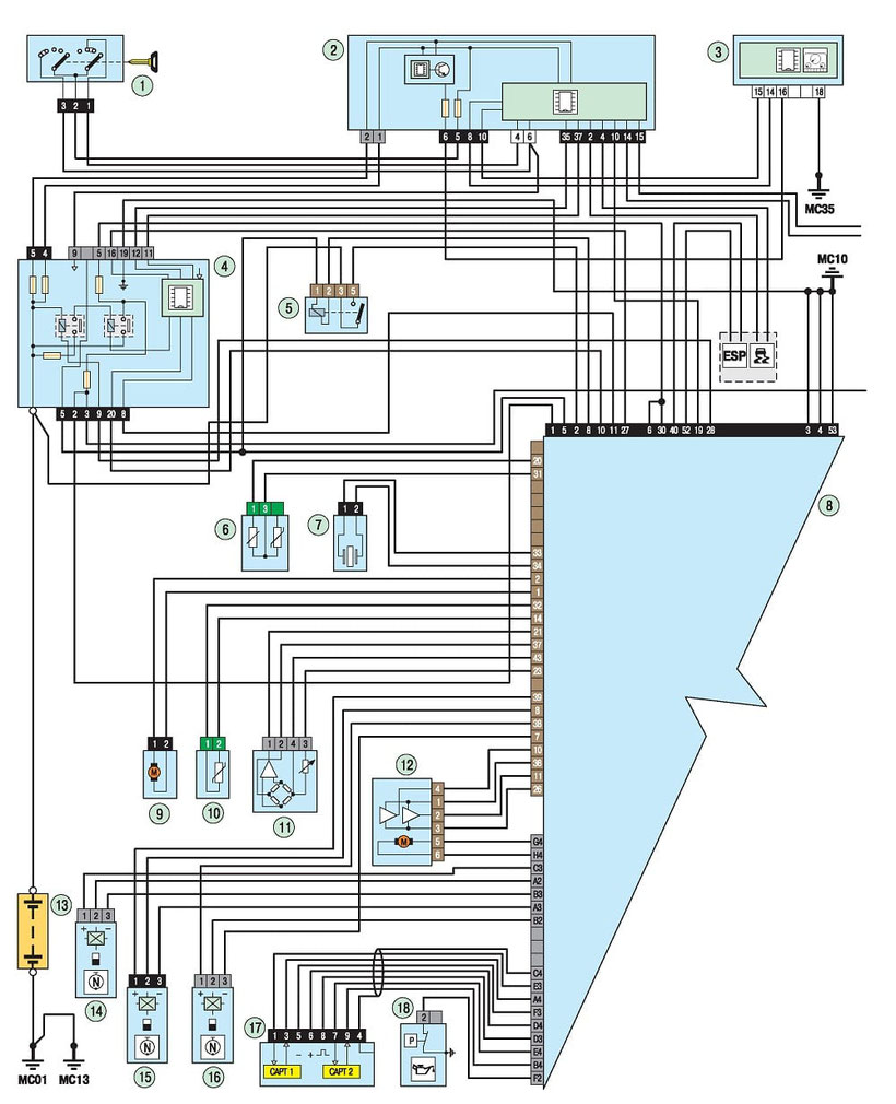
308 Engine Management System Wiring Diagram
1 - ignition lock; 2 - BSI; 3 - instrument panel; 4 - mounting the engine compartment; 5 - motor control relay; 6 - temperature sensor and engine oil level; 7 - knock sensor; 8 - engine control unit; 9 - electric drive; 10 - coolant temperature sensor; 11 - absolute pressure sensor; 12 - throttle position sensor; 13 - rechargeable battery; 14 - camshaft position sensor №1; 15 - crankshaft position sensor; 16 - camshaft position sensor №2; 17 - valve system for changing the height of the valves; 18- oil pressure sensor
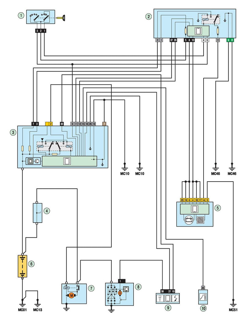
308 Starter and Generator Diagram
1- ignition lock; 2-unit electrical control unit; 3-assembly unit in the engine compartment; 4-assembly unit in the cabin; 5- instrument cluster; 6 - rechargeable battery; 7 - starter; 8- generator; 9 - engine control unit; 10 - the lever of the selector of management of an automatic transmission
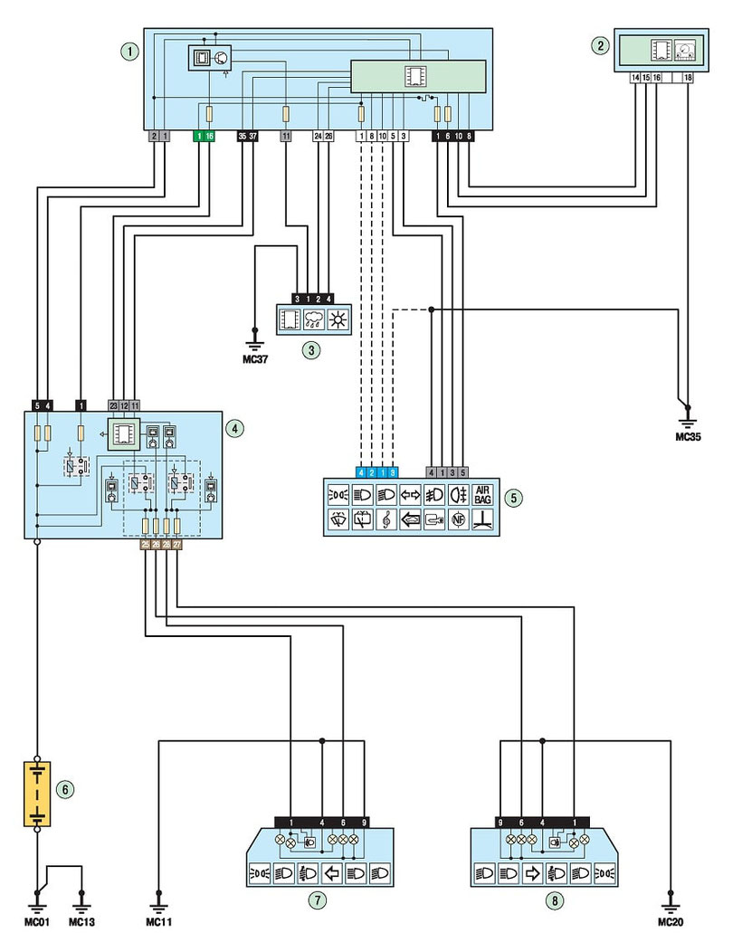
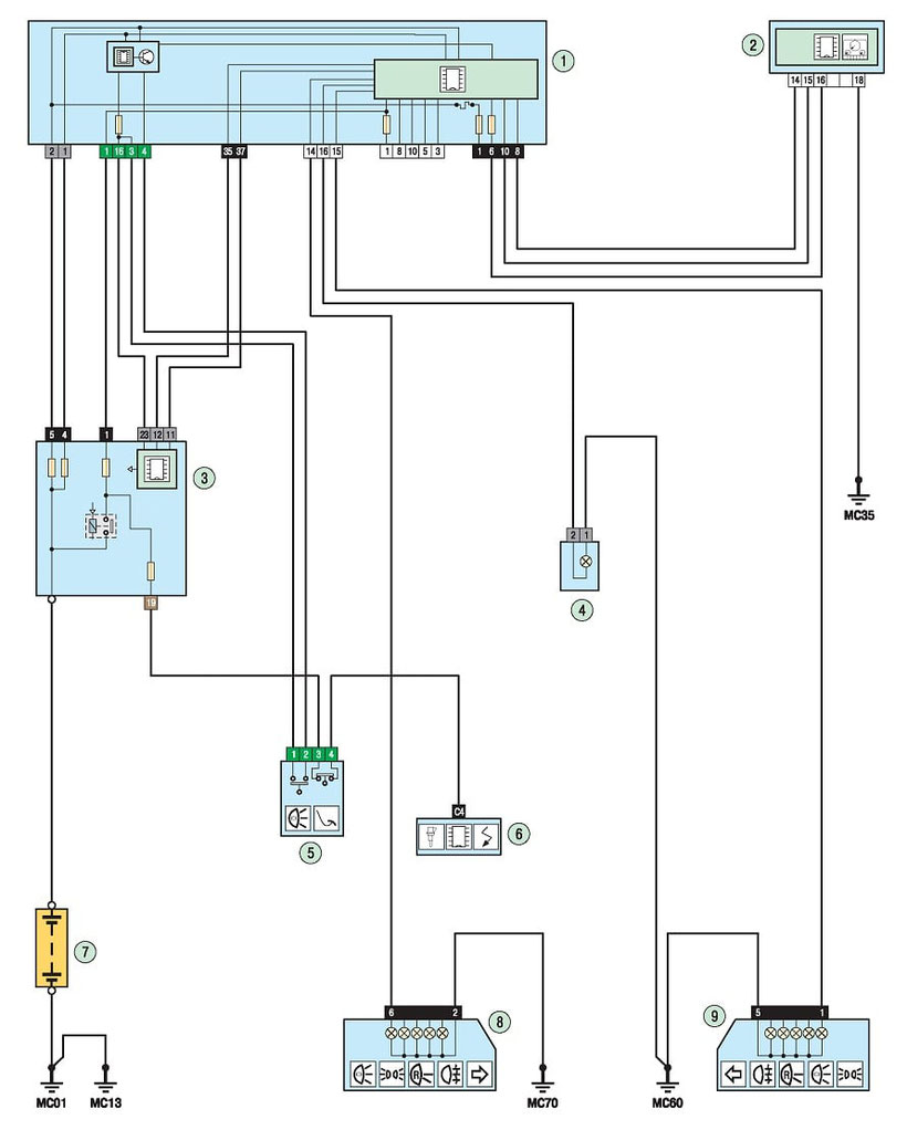
308 Low and High Beam Headlights Schematics
1 - electrical control unit; 2 - instrument panel; 3 - rain sensors and the intensity of solar radiation; 4 - mounting block in the engine compartment; 5 - block steering column switches; 6 - rechargeable battery; 7 - left headlight; 8 - right headlight
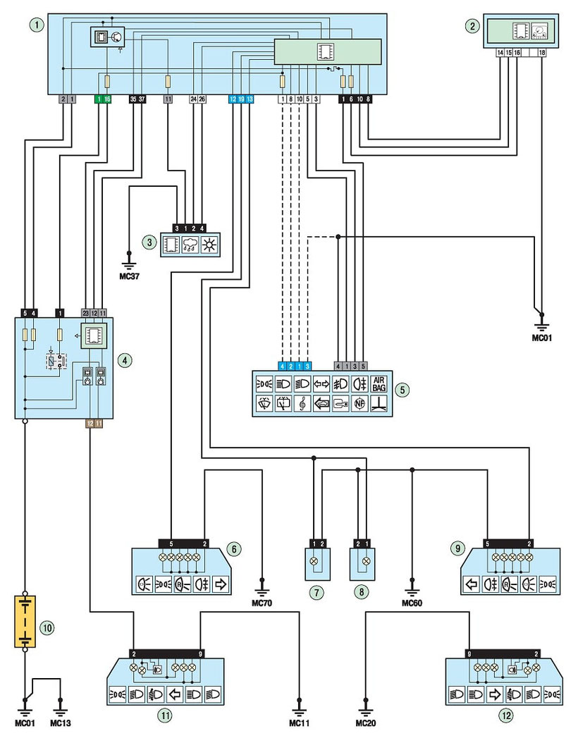
308 Parking Lights Wiring Diagram
1 - electrical control unit; 2 - instrument panel; 3 - rain sensors and the intensity of solar radiation; 4 - mounting block in the engine compartment; 5 - block steering column switches; 6 - right rear light; 7 - the left license plate lamp; 8 - right license plate light; 9 - left rear light; 10 - rechargeable battery; 11 - left headlight; 12 - right headlight
308 Brake Lights Scheme
1 - electrical control unit; 2 - instrument panel; 3 - mounting the engine compartment; 4 - additional brake light; 5 - brake light switch; 6 - engine control unit; 7 - rechargeable battery; 8 - right rear light; 9 - left rear light

